BELIEVE ME NOT! -  - A SKEPTIC's GUIDE


Next: About this document . . .
Up: Interference in Space
Previous: Interference in Space
What happens when coherent light comes through more than two slits,
all equally spaced a distance  apart, in a line parallel to the
incoming wave fronts? The same criterion (46)
still holds for completely constructive interference
(what we will now refer to as the PRINCIPAL MAXIMA)
but (47) is no longer a reliable criterion
for destructive interference: each successive slit's
contribution cancels out that of the adjacent slit,
but if there are an odd number of slits, there is still
one left over and the combined amplitude is not zero.
Does this mean there are no angles where the intensity goes to zero?
Not at all; but it is not quite so simple to locate them.
One way of making this calculation easier to visualize
(albeit in a rather abstract way) is with the geometrical
aid of PHASORS:
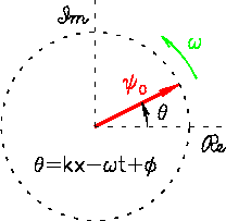
Figure:
A single "PHASOR" of length  (the wave amplitude)
precessing at a frequency
  in the complex plane.
 |
A single wave can be expressed as
 where
where
 is the phase
of the wave at a fixed position
  at a given time
  .
(As usual,
  is the "initial" phase at
  and
and  .
At this stage it is usually ignored;
I just retained it one last time for completeness.)
If we focus our attention on one particular location in space,
this single wave's "displacement"
  at that location
can be represented geometrically as
a vector of length
  (the wave amplitude)
in the complex plane called a "PHASOR"
As time passes, the "direction" of the phasor rotates
at an angular frequency
  in that abstract plane.
There is not much advantage to this geometrical description
for a single wave
(except perhaps that it engages the right hemisphere of the brain
a little more than the algebraic expression)
but when one goes to "add together" two or more waves
with different phases, it helps a lot!
Figure:
Two waves of equal amplitude  but different phases
 and
and  are represented as PHASORS
in the complex plane. Their vector sum has the resultant
amplitude
 and the average phase
  .
.
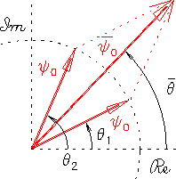 |
For example, two waves of equal amplitude but different phases
can be added together algebraically as in Eq. (45)
where
That is, the combined amplitude
 can be obtained
by adding the phasors "tip-to-tail" like ordinary vectors.
Like the original components, the whole thing continues to
precess in the complex plane at the common frequency
  .
.
We are now ready to use PHASORS to find the amplitude of
an arbitrary number of waves of arbitrary amplitudes and phases
but a common frequency and wavelength
interfering at a given position.
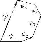
This is illustrated in Fig. 14.17
for 5 phasors.
Figure:
The net amplitude of a wave produced by the interference of
an arbitrary number of other waves of the same frequency
of arbitrary amplitudes  and phases
  can in principle be calculated geometrically by
"tip-to-tail" vector addition of the individual
PHASORS in the complex plane.
 |
In practice, we rarely attempt such an arbitrary calculation,
since it cannot be simplified algebraically.
Instead, we concentrate on simple combinations of waves of
equal amplitude with well defined phase differences, such as
those produced by a regular array of parallel slits with an
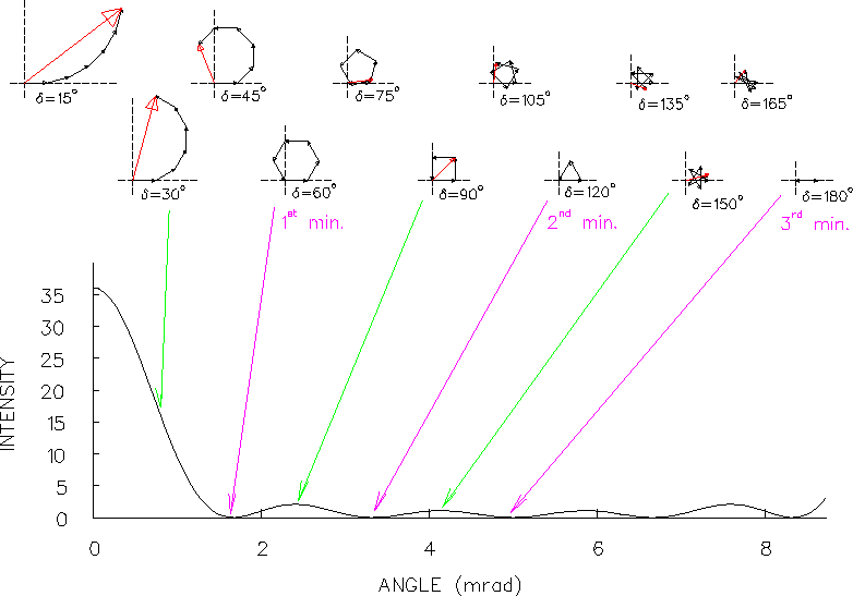
equal spacing between adjacent slits. Figure 14.18
shows an example using 6 identical slits with a spacing
 . The angular width of the interference pattern
from such widely spaced slits is quite narrow, only 10 mrad
(
 radians) between principal maxima where all 6
rays are in phase. In between the principal maxima there are
5 minima and 4 secondary maxima; this can be generalized:
![\fbox{ \parbox{3.0in}{~\\
The interference pattern for $N$\ equally spaced sli . . .
. . . ary maxima\/}
between each pair of principal maxima. \\ [-0.5\baselineskip]} }](img287.png)
Figure:
The intensity pattern produced by the interference of coherent light
passing through six parallel slits 100 wavelengths apart.
PHASOR DIAGRAMS are shown for selected angles.
Note that, while the phase angle difference  between rays from adjacent slits is a monotonically increasing
function of the angle
  (plotted horizontally)
that the rays make with the "forward" direction,
the latter is a real geometrical angle in space while the former is
a pure abstraction in "phase space".
The exact relationship is
 for very small
  .
Note the symmetry about the
  minimum
at
 mrad.
At
 mrad the intensity is back up to the
same value it had in the central maximum at
  ;
this is called the first PRINCIPAL MAXIMUM.
Then the whole pattern repeats . . . .
 |
It may be conceptually helpful to show the geometrical explanation
of the 6-slit interference pattern in Fig. 14.18
in terms of phasor diagrams, but clearly the smooth curve shown there
is not the result of an infinte number of geometrical constructions.
It comes from an algebraic formula that we can derive for an arbitrary
angle  and a corresponding phase difference
 between rays from adjacent slits.
The formula itself is obtained by analysis of a geometrical construction
like that illustrated in Fig. 14.19 for 7 slits,
each of which contributes a wave of amplitude
  ,
with a phase difference of
  between adjacent slits.
Figure:
PHASOR DIAGRAM for calculating the intensity pattern
produced by the interference of coherent light
passing through 7 parallel, equally spaced slits.
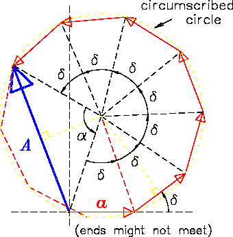 |
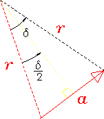
Figure:
Blowup of one of the isosceles triangles formed by a single
phasor and two radii from the center of the circumscribed circle
to the tip and tail of the phasor.
 |
After adding all 7 equal-length phasors in Fig. 14.19
"tip-to-tail",
we can draw a vector from the starting point to the tip of
the final phasor. This vector has a length  (the net amplitude)
and makes a chord of the circumscribed circle, intercepting an angle
 |
(14.50) |
where in this case  .
The radius
  of the circumscribed circle is given by
 |
(14.51) |
as can be seen from the blowup in Fig. 14.20;
this can be combined with the analogous
 |
(14.52) |
to give the net amplitude
![\begin{displaymath}
A = a \, \left[ \sin \left( \alpha \over 2 \right)
\over \sin \left( \delta \over 2 \right) \right] \; .
\end{displaymath}](img303.png) |
(14.53) |
From Eq. (50) we know that
 ,
and in general
 , so
, so
![\begin{displaymath}
\mbox{
\fbox{ \rule[-1.0\baselineskip]{0pt}{2.5\baselineski . . .
. . . )
\over \sin \left( \delta \over 2 \right) \right]
}$~
}}
\end{displaymath}](img306.png) |
(14.54) |
where
![\begin{displaymath}
\mbox{
\fbox{ \rule[-1.0\baselineskip]{0pt}{2.5\baselineski . . .
. . . \pi \left( d \over \lambda \right) \, \sin \vartheta
}$~
}}
\end{displaymath}](img307.png) |
(14.55) |
Although the drawing shows  phasors, this result is valid for
an arbitrary number
  of equally spaced and evenly illuminated slits.


Next: About this document . . .
Up: Interference in Space
Previous: Interference in Space
Jess H. Brewer
2002-03-26
 - A SKEPTIC's GUIDE
  - A SKEPTIC's GUIDE
 ![]() apart, in a line parallel to the
incoming wave fronts? The same criterion (46)
still holds for completely constructive interference
(what we will now refer to as the PRINCIPAL MAXIMA)
but (47) is no longer a reliable criterion
for destructive interference: each successive slit's
contribution cancels out that of the adjacent slit,
but if there are an odd number of slits, there is still
one left over and the combined amplitude is not zero.
apart, in a line parallel to the
incoming wave fronts? The same criterion (46)
still holds for completely constructive interference
(what we will now refer to as the PRINCIPAL MAXIMA)
but (47) is no longer a reliable criterion
for destructive interference: each successive slit's
contribution cancels out that of the adjacent slit,
but if there are an odd number of slits, there is still
one left over and the combined amplitude is not zero.


![]() . The angular width of the interference pattern
from such widely spaced slits is quite narrow, only 10 mrad
(
. The angular width of the interference pattern
from such widely spaced slits is quite narrow, only 10 mrad
(![]() radians) between principal maxima where all 6
rays are in phase. In between the principal maxima there are
5 minima and 4 secondary maxima; this can be generalized:
radians) between principal maxima where all 6
rays are in phase. In between the principal maxima there are
5 minima and 4 secondary maxima; this can be generalized:
![\fbox{ \parbox{3.0in}{~\\
The interference pattern for $N$\ equally spaced sli . . .
. . . ary maxima\/}
between each pair of principal maxima. \\ [-0.5\baselineskip]} }](img287.png)

![]() and a corresponding phase difference
and a corresponding phase difference
![]() between rays from adjacent slits.
The formula itself is obtained by analysis of a geometrical construction
like that illustrated in Fig. 14.19 for 7 slits,
each of which contributes a wave of amplitude
between rays from adjacent slits.
The formula itself is obtained by analysis of a geometrical construction
like that illustrated in Fig. 14.19 for 7 slits,
each of which contributes a wave of amplitude ![]() ,
with a phase difference of
,
with a phase difference of ![]() between adjacent slits.
between adjacent slits.


![]() (the net amplitude)
and makes a chord of the circumscribed circle, intercepting an angle
(the net amplitude)
and makes a chord of the circumscribed circle, intercepting an angle
![]() phasors, this result is valid for
an arbitrary number
phasors, this result is valid for
an arbitrary number ![]() of equally spaced and evenly illuminated slits.
of equally spaced and evenly illuminated slits.