In Fig. ![]() there are a row of light-triggered bombs
spaced at equal intervals along the x axis; as the beam of light
emitted at t=0 hits each of these in turn, there is an explosive
event at a position indicated by an asterisk
along the worldline of the light ray.
In order to avoid direct logical contradictions,
observers O (at rest) and O' (moving) must agree
that these events take place at equal intervals
in both time and space, and that the ratio of each spatial interval
(
there are a row of light-triggered bombs
spaced at equal intervals along the x axis; as the beam of light
emitted at t=0 hits each of these in turn, there is an explosive
event at a position indicated by an asterisk
along the worldline of the light ray.
In order to avoid direct logical contradictions,
observers O (at rest) and O' (moving) must agree
that these events take place at equal intervals
in both time and space, and that the ratio of each spatial interval
( for O,
 for O')
to the corresponding time interval
(
for O')
to the corresponding time interval
( or
or
 , respectively)
must equal the speed of light:
, respectively)
must equal the speed of light:

However, both the spatial interval
and the time interval
are
smaller
in the moving reference frame -- from the point of view of O',
the bombs are closer together (Lorentz contraction) and therefore
of course the light reaches them in shorter times.![]() This means that loci of equal time in the moving reference frame
(lines parallel to the x' axis) and
loci of constant position
in the moving reference frame (lines parallel to the ct'
are not at right angles any more when plotted on the same
graph as the x and ct axes.
This means that loci of equal time in the moving reference frame
(lines parallel to the x' axis) and
loci of constant position
in the moving reference frame (lines parallel to the ct'
are not at right angles any more when plotted on the same
graph as the x and ct axes.
Another way of putting it is that you cannot use a ruler
to measure the ``distance" between two ``points" on such a diagram
the same way you can in Fig.
![]() ,
because Minkowski space does not obey Euclidean geometry,
the most fundamental property of which is Eq.
(
,
because Minkowski space does not obey Euclidean geometry,
the most fundamental property of which is Eq.
(![]() ).
Instead, the ``metric" of spacetime is defined by
Eq. (
).
Instead, the ``metric" of spacetime is defined by
Eq. (![]() ),
which does not treat the time dimension
the same way as the space dimension!
),
which does not treat the time dimension
the same way as the space dimension!
So diagrams like Fig.
![]() are not very helpful
for actually solving problems; they serve mainly to illustrate
the danger in taking a graphical representation too
seriously: the paper on which Fig.
are not very helpful
for actually solving problems; they serve mainly to illustrate
the danger in taking a graphical representation too
seriously: the paper on which Fig.
![]() is drawn obeys a different metric (the Euclidean metric) from
the actual spacetime it is meant to represent!
To see just how confusing this can become, try constructing
the inverse Lorentz transformation graphically:
treating the observer O' as the rest
frame and the observer O
as moving in the negative x direction at a speed u,
construct a diagram analogous to Fig.
is drawn obeys a different metric (the Euclidean metric) from
the actual spacetime it is meant to represent!
To see just how confusing this can become, try constructing
the inverse Lorentz transformation graphically:
treating the observer O' as the rest
frame and the observer O
as moving in the negative x direction at a speed u,
construct a diagram analogous to Fig.
![]() in which the x' and ct'
axes are orthogonal.
What do the x and ct axes look like in the
O' rest frame?
in which the x' and ct'
axes are orthogonal.
What do the x and ct axes look like in the
O' rest frame?
This lack of a simple, symmetric, reversible geometrical transformation like the 2D rotation is an inescapable feature of Lorentz transformations. We have to find other ways of approaching problems in . Unfortunately for many who (like me) are especially fond of their right hemispheres, those ways are mainly mathematical and analytically abstract. However, there are still a few graphical techniques we can use safely if we are careful.
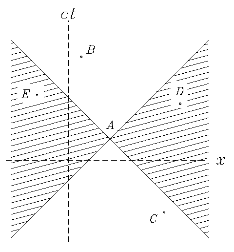
Figure: At any event A in spacetime,
the boundary of all possible events
(such as events B and c)
that could in principle be causally connected to A
(either causes of A in the past
or effects of A in the future,
relative to A) is defined by the locus of all possible
worldlines of light rays starting or ending at A.
This locus is the 4-dimensional analogue
of a cone, in which the axis of symmetry
is the time axis and the other 3 axes are x,y and z.
Since we cannot draw such a locus on paper,
we content ourselves with its projection onto the
x-ct ``plane," ignoring the other two spatial dimensions.
This graphical device is known as the ``light cone"
even though on this diagram it just looks like
some oblique lines through A at ±45°.
Events in the shaded region (such as events D and E)
cannot have any causal connection to event A.